How to do FEA analysis for 3D printed parts
FDM 3D printing is a nice way to quickly prototype ideas and designs- especially when you are a startup and might want to launch a product which is still 3D printed. Knowing failing conditions is necessary for any mechanical part, especially for the functional ones. However, I was surprised I couldn’t find anywhere a good model to predict failure for 3D printed parts.
I decided to collect data from some samples and their failure tests, and see if I can create a crude model to compute failure. This would also help choose suitable features for modeling parts. (Spoiler: the simulation results with tweaked params get pretty close to empirical data.)
Test parts
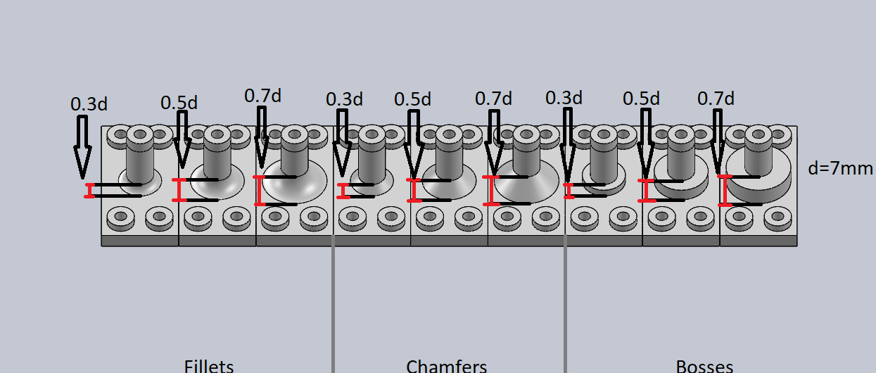
I designed multiple variations of the test part- with the strength-adding feature being fillets, chamfers and bosses, and for each of them having 3 variations where the feature diameter
D = a × d, a ∈ [0.3, 0.5 0.7]
(d = diameter of the cylindrical section)
Each variation has 3 duplicates to repeat the tests. That is, a total of 27 test parts:
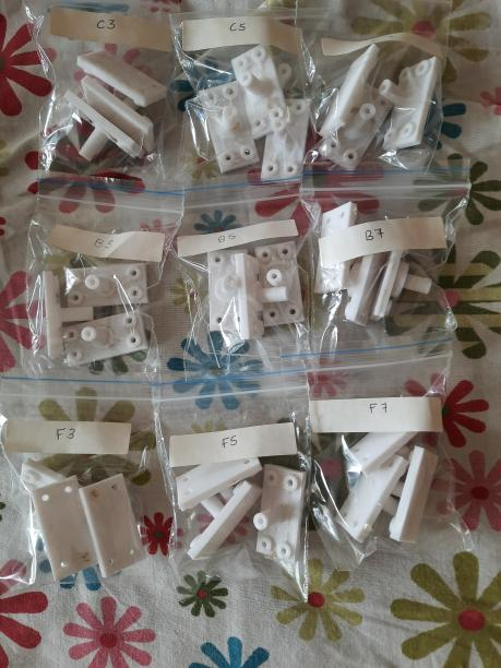
Print attributes: FDM printer with hotbed, 0.4mm nozzle, 1.75mm PLA filament.
Setup
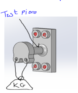
The test part is bolted to a test board acting as a wall. The measuring scale is connected to the part using a connector at the edge. Pulling down on the scale is a proxy to manually adding weights. The scale gives the force applied just before breaking, and offers better resolution than adding weights would. Besides, I didn’t have the weights!
Results
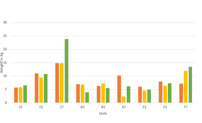
Based on my experiment, if you want better strength, use chamfers! The larger the feature, the better it performs. The third test for C7 is a bit questionable, but even if you remove the outlier, C7 consistently produced better results than others.
Transforming the model
Now, we have the empirical data. I now had to tweak the FEA and model params to get close to this data (never knew I’d be performing regression on mechanical parts!).
The major change you need to do is convert your part into a hollow shell with thickness equal to what you choose as shell thickness when slicing your part (using Simplify3D, for example). Then the static load analysis, using the Von Mises Failure Criterion on SolidWorks outputs roughly the same results.
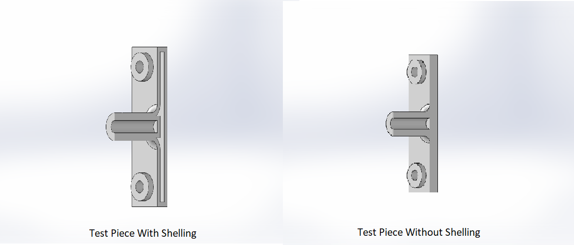
So, to perform FEA on 3D printed parts, convert it into shells. Makes sense, as 3D parts are essentially shells, with very low infill (usually 15%).
If you’re curious, you can take a look at the data I collected here.
Next steps
This experiment is still long way from generalizing the result. Quite a few more experiments can be done by varying parameters like nozzle diameter, print material, part orientation, print temperature, and more.